Super Clamp TVS – Solution with an extremely low clamping ratio
Super Clamp TVS – Solution with an extremely low clamping ratio
February 14, 2025
Category: Blog
Taiwan semiconductor introduces, first of its kind, transient voltage suppressor (TVS) called Super Clamp TVS.
Super Clamp TVS adopts snapback characteristics which is beneficial to extremely low clamping ratio between working voltage (VWM) and clamping voltage (VC). The low clamping ratio TVS can suppress high surge current to provide lower clamping voltage than conventional TVS and metal oxide varistor (MOV), which means designer could use lower working voltage components of capacitor, switching MOSFET, reverse polarity protection diodes, and regulators.
Super Clamp TVS breakdown voltage (VBR) difference of temperature deviation is lower than conventional TVS. This VBR stability by temperature variation helps designer anticipate voltage range when adding in temperature consideration.
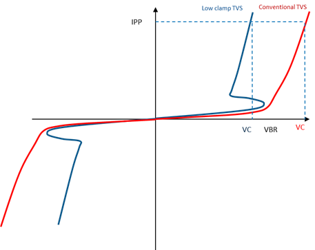
Super Clamp TVS structure
Super Clamp TVS adopts BJT (Bipolar junction transistor) which is different from conventional TVS as shown in Figure 1. When breakdown voltage occurs for Super Clamp TVS, due to its instinctive snapback characteristics, it foldbacks and then breakdown happens again. This low clamp ratio provides lower VC (clamping voltage) at high IPP (peak impulse current), which means the discrete components, which come after the Super Clamp TVS, could sustain lower voltage stress and designer could use lower working voltage specification components like capacitor, MOSFET etc.
Conventional TVS and Super Clamp TVS structure, VC – IPP curve
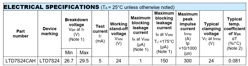
TSC high power DO-218AB package Super Clamp TVS specification:
Fan Single phase H-bridge BLDC motor usage component
Comparison
In order to understand Super Clamp TVS characteristics and advantages over conventional TVS, take DO-218AB package bi-directional Super Clamp TVS LTD7S24CAH of TaiwanSemi and DO-218AB package uni-directional conventional TVS TLD8S24AH of TaiwanSemi to do the comparison.
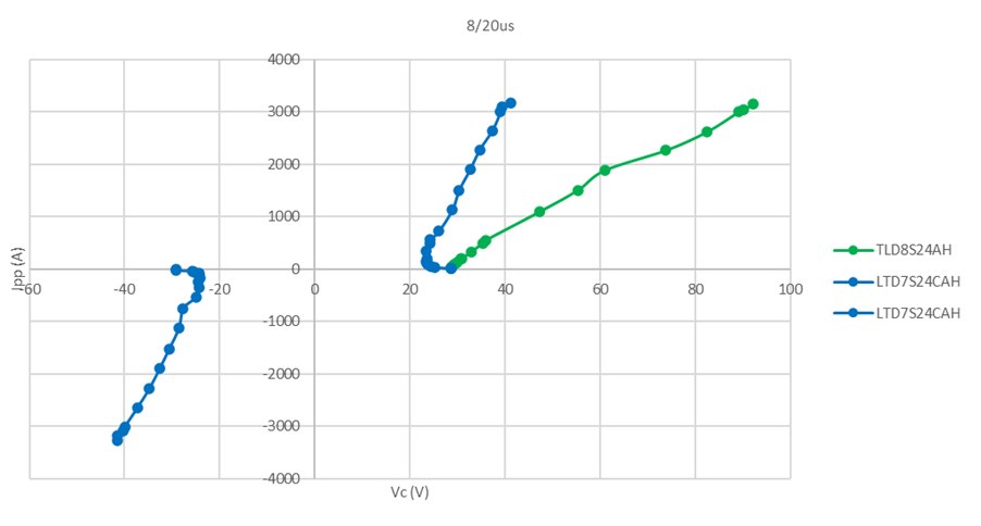
8/20us I-V curve comparison
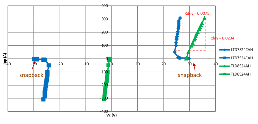
Taking Super Clamp TVS LTD7S24CAH and conventional TVS TLD8S24AH to test 8/20us transient surge and recording VC – IPP waveform as shown in Figure 2. LTD7S24CAH curve shows snapback characteristics whose VC clamping ratio is 1.63 (VC/VWM) and Rdny is 0.0058 ohm, which are lower than those of TLD8S24AH. TLD8S24AH curve shows exponential characteristics and whose VC clamping ratio is 3.78 (VC/VWM) and Rdny is 0.0224 ohm. Super Clamp TVS can suppress transient surge closer to VBR than conventional TVS.
Super Clamp TVS LTD7S24CAH and conventional TVS TLD8S24AH 8/20us I-V curve
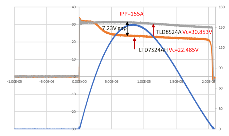
VC tested by 8/20us IPP comparison
Taking Super Clamp TVS LTD7S24CAH and conventional TVS TLD8S24AH to test 8/20us transient surge. Applying 8/20us of IPP=155A to these two TVS and recording VC results as in Figure 3. LTD7S24CAH VC (23.623V) is 76.56% of TLD8S24A VC (30.853V).
Super Clamp TVS LTD7S24CAH and conventional TVS TLD8S24AH tested 8/20u IPP=155A
10/1000us I-V curve comparison
Taking Super Clamp TVS LTD7S24CAH and conventional TVS TLD8S24AH to test 10/1000us transient surge and recording VC – IPP waveform as shown in Figure 4. LTD7S24CAH curve shows snapback characteristics whose VC clamping ratio is 1.049 (VC/VWM) and Rdny is 0.0075 ohm, which are lower than those of TLD8S24AH. TLD8S24AH curve shows exponential characteristics whose VC clamping ratio is 1.349 (VC/VWM) and Rdny is 0.0234 ohm. Super Clamp TVS can suppress transient surge closer to VBR than conventional TVS.
Super Clamp TVS LTD7S24CAH and conventional TVS TLD8S24AH 10/1000us I-V curve
Device VBR temperature deviation comparison
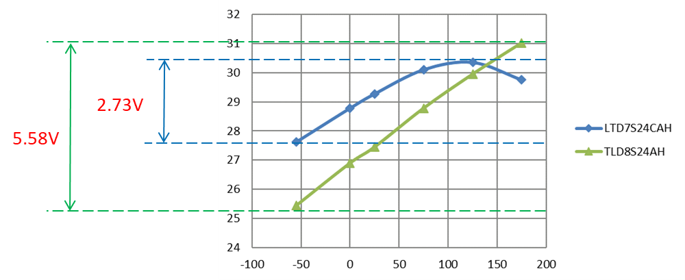
VBR will be a focus point for a designer if TVS inadequately turns on when temperature is increasing. Taking Super Clamp TVS LTD7S24CAH and conventional TVS TLD8S24AH to test VBR in temperature range -55⁰C to 175⁰C as shown in Figure 8. For LTD7S24CA, when operating in temperature range -55⁰C to 175⁰C, VBR deviation difference is 2.73V; For TLD8S24A, when operating in temperature range -55⁰C to 175⁰C, VBR deviation difference is 5.58V. So, for LTD7S24CA VBR difference of temperature deviation is more stable than TLD8S24A.
LTD7S24CAH VBR temperature variation is lower than TLD8S24AH
Potential application example– BLDC FAN
Back-EMF threat
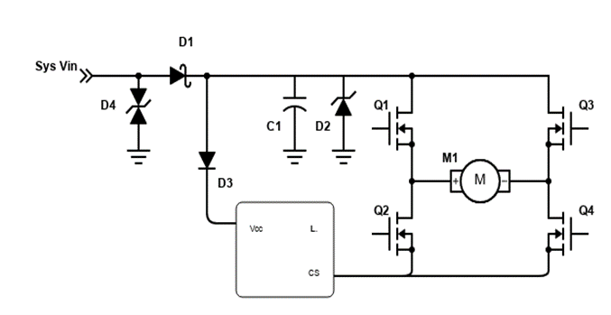
24V industry Fan uses Single phase H-bridge BLDC motor circuit as shown in Figure 6. The motor exhibits Back-EMF (Back Electromotive Force) when in operation. When current flows through motor, Back-EMF will flow to voltage source while motor decelerates or stops and it might damage front components like MOSFET.
Single phase H-bridge BLDC motor circuit
Advantage
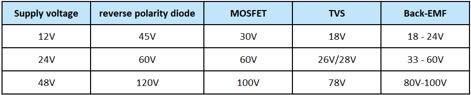
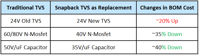
Normally the components selection for industry Fan Single phase H-bridge BLDC motor needs to consider Back-EMF robustness as shown in Table 2. 24V motor will have 60V Back-EMF threat and it will use TVS with VBR=28V to clamp this Back-EMF to 33V for protecting the 60V MOSFET. If it adopts Super Clamp TVS LTD7S24CAH, it could clamp Back-EMF to 25V. That brings benefits: 60V MOSFET may exchange to 40V MOSFET and 50V Capacitance may exchange to 35V Capacitance.
Fan Single phase H-bridge BLDC motor usage component
Though it is completely dependent on end application, a general estimate for BOM cost reduction can be estimated from below table.
Fan Single phase H-bridge BLDC motor usage component
Conclusion
Super Clamp TVS adopts snapback technology and its low VC could help protect discrete components sustain lower voltage stress, based on application design, compared to conventional TVS. That helps downsizing components rating and eventually BOM cost reduction.
Author’s Profile
Muhammad Ahad Rafiq
Taiwan Semiconductor Senior Field Application Engineer